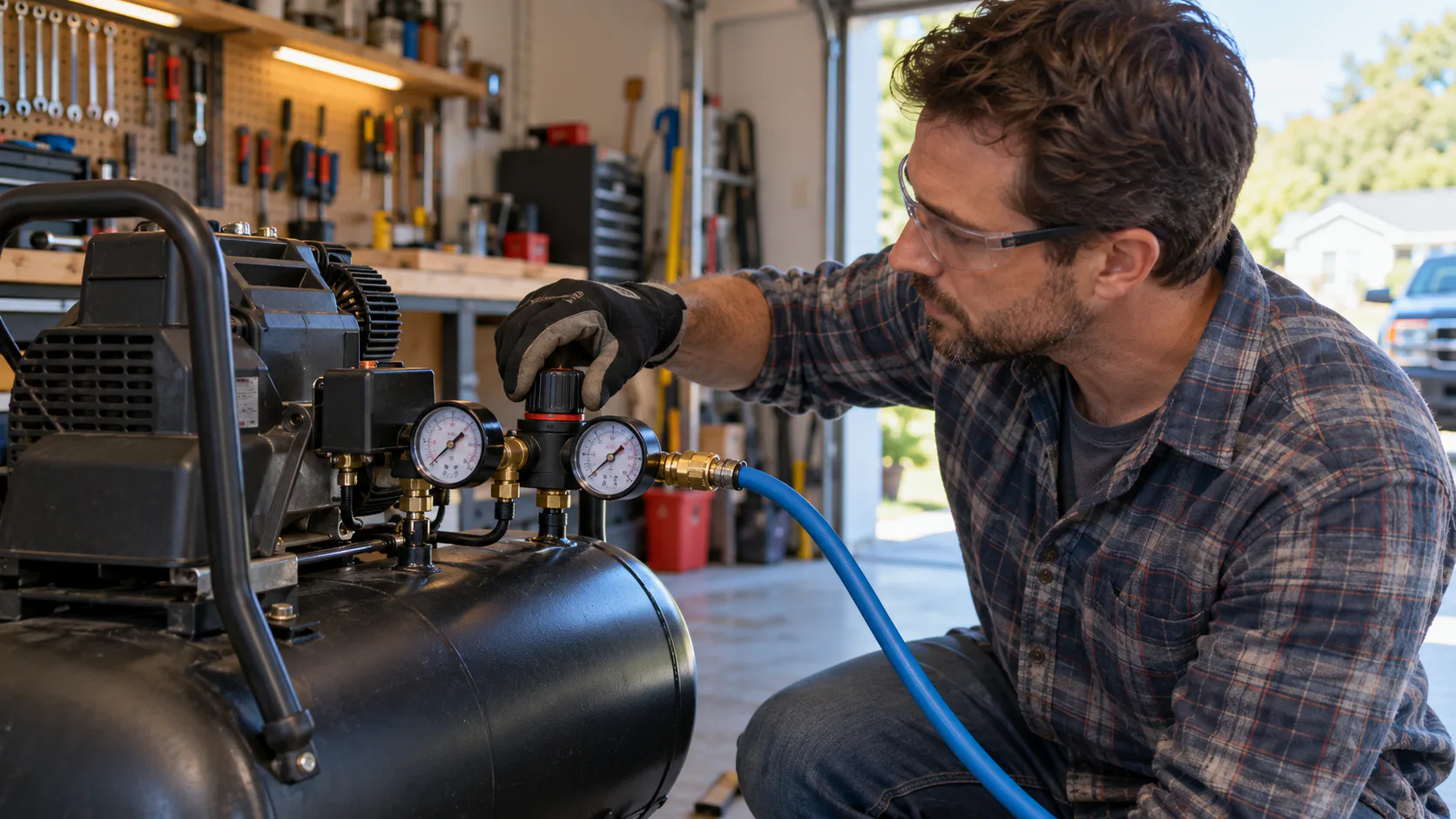
The two gauges measure different parts of the system
On a typical portable compressor, one gauge reports pressure stored in the receiver tank. The other reports pressure downstream of the regulator. The regulator lets the tank hold a higher reserve while the connected tool receives the operating pressure selected for that air line.
That difference is intentional. A tank reading of 125 PSI and an outlet setting near 90 PSI can be normal when both figures are within the exact compressor, hose and tool limits. The tank gauge is not a recommendation for tool pressure.
Gauge layouts vary. Some units use labels or icons; others place the gauges close enough to be confusing. Identify each gauge from the compressor manual before changing the regulator.
What the regulator does
A pressure regulator reduces and controls downstream pressure. Turning its adjustment changes spring force inside the regulator, which changes how the valve responds as downstream pressure rises or falls. The mechanism continually balances the selected setting against the pressure on the outlet side.
This is pressure control rather than an isolation barrier. Air still moves through the regulator when the connected tool consumes it. The regulator also has a finite flow capacity, so a small regulator asked to feed a high-demand tool can become a restriction.
EXAIR's regulator explanation describes this balance through a spring, diaphragm and valve assembly. You do not need to open that assembly to use it. If a regulator will not hold a stable setting, follow the compressor's replacement procedure or use qualified service.
Static pressure and pressure while flowing
The outlet gauge can show the selected pressure while the tool is idle, then fall when the trigger is pulled. The idle reading is static pressure. The reading while the tool consumes air is the useful flowing or dynamic reading.
Ingersoll Rand instructs users to check operating pressure at the tool inlet while the tool is running for supported pneumatic tools. This matters because the compressor gauge is upstream of the hose, couplers and any filter or lubricator. Each part can consume some of the available pressure while air flows.
A falling outlet reading can have several causes:
- the regulator needs adjustment within the equipment limits;
- the regulator or filter is undersized, clogged or damaged;
- the hose is too long or has too small an inside diameter;
- a coupler or fitting creates a restriction;
- the system has a leak;
- the compressor is replacing air more slowly than the tool is using it.
The gauge difference alone does not identify which cause is present.
A practical check from tank to tool
Use the air path in order instead of turning the pressure up repeatedly.
- Identify the gauges. Confirm which one reports receiver pressure and which one reports regulated outlet pressure.
- Find the tool limit. Read the exact tool manual for operating pressure and maximum pressure.
- Set the outlet. Adjust the regulator only within every connected component's rating.
- Check under flow. Use a suitable gauge at or near the tool inlet while the tool runs if the manual calls for an inlet-pressure check.
- Move upstream. If pressure is low at the tool, inspect couplers, hose diameter and length, filters and the regulator.
- Check delivery. Compare the tool's published airflow field with the compressor's published delivery at the same stated pressure, keeping CFM and SCFM labels visible.
Our guide to hose length and inside diameter explains the downstream restriction check. The same-pressure comparison guide covers the delivery check.
When the tank gauge also falls
Receiver pressure normally moves between the compressor's cut-in and cut-out settings. The motor starts when tank pressure reaches the lower switch threshold and stops at the upper threshold. The outlet regulator does not change those factory switch settings.
If the tank pressure falls steadily while a tool runs, the tool and any leaks may be drawing air faster than the pump replaces it. A larger receiver can extend a short burst, but it does not increase the pump's delivery rate.
If the receiver reaches its normal range while the tool-side pressure still collapses, the restriction is more likely downstream of the tank. A clogged filter, narrow coupler, damaged regulator or undersized hose can produce that pattern.
Do not use pressure to hide an airflow problem
Many pneumatic tools list an operating pressure around 90 PSI, but the exact model controls. Ingersoll Rand warns users not to exceed the maximum operating pressure stated for the tool.
Raising outlet pressure may briefly change tool behavior while increasing stress on the tool and every component in the air path. Keep the regulator within the lowest applicable rating. If stable pressure cannot be maintained at the required flow, repair the restriction or choose a supply with suitable delivery.
Use the Air Tool Match calculator to place published tool consumption and compressor delivery fields beside each other at the same stated pressure. It does not calculate losses through your regulator, hose or fittings, so the flowing-pressure check remains part of the diagnosis.
Sources checked
- What Is Static and Dynamic Air Pressure?, Ingersoll Rand, checked 2026-10-12
- How a Pressure Regulator Works, EXAIR, checked 2026-10-12
- Improving Compressed Air System Performance, Compressed Air Challenge, checked 2026-10-12
Technical pages can change. Confirm control layout, working pressure and maximum pressure in the exact equipment manuals.